

PRODUCT OVERVIEW
The TouchswitchTM is an electronic limit switch. When a belt misaligns or a pulley moves over and contacts the sensor, the built in solid-state electronic circuitry detects the lateral force of the belt or pulley and activates a voltage free relay contact. This relay contact is used to immediately alarm and shutdown the machine. The face of the sensor is made from hardened stainless steel, so that there is virtually no wear when a belt contacts it. The sensor is not affected by dust or material build up and will still work when completely covered by material. Sensors are normally installed in pairs on opposite sides of the machine. Usually a pair of sensors at each pulley is used, but additional pairs can be installed as required. An external test knob allows for quick and simple sensor / system testing.
SPECIFICATIONS
50 mA (TS2V4AI) / 60 mA (TS2V3AI)
Factory set to 8 lb. (3.6 Kg) approximately
Hardened stainless steel (face) and seamless steel with epoxy paint (body) 1.4 Kg (3 lbs.)
Power Consumption - Sensing Force - Construction -
Weight -
Approvals -
IECEx
Ex tb IIIC T80°C Db IP66 Tamb -20°C 40°C IECEx BAS13.0116X
ATEX
Ex II 2D Ex tb IIIC T80°C Db IP66 Tamb -20°C 40°C Baseefa14ATEX0015X
EACEx
Ex tb IIIC T80°C Db X
RU C-GB.Aж58.B.00346/20
CCCEx
Ex tD A21 IP66 T80°C CQC-2020012304351294
SPECIAL CONDITIONS FOR SAFE USE
1. Do not allow dust layers to build up on this product.
2. The sensor shall be connected to a suitable external earth via the mounting arrangement or via the flange and a suitable ring crimp lug and accessories.
3. The integral cable shall be terminated in a suitably certified enclosure or in a safe area.
4. The supply to the equipment must not exceed the rated voltage.
PAGE 6
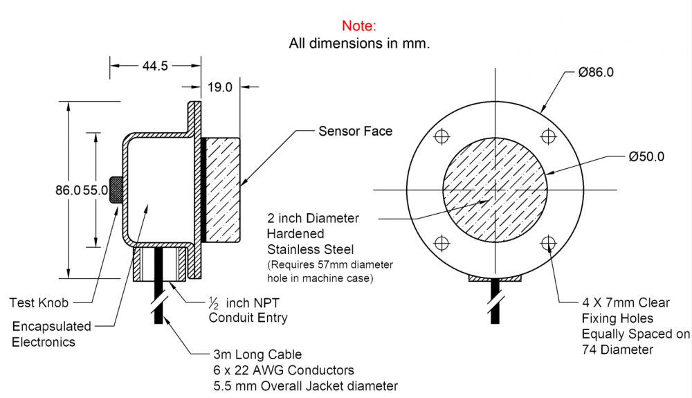
DIMENSIONS
INSTALLATION
The following are guidelines and suggestions for installing Touchswitches. The installer must take responsibly that the Touchswitches are mounted in a position to be able to detect a belt misalignment condition and or a pulley misalignment condition, whichever it may be. Typical TouchswitchTM mounting positions are illustrated on pages 10 - 15.
The TouchswitchTM hole should be cut into the housing with a 57mm diameter hole saw (Image A), centered on the edge of the belt. The hole should be cleaned and de-burred to avoid the TouchswitchTM puck binding and giving false misalignment alarms. You can mount the TouchswitchTM with 2 of the 4 flange holes, provided they are diagonal from one another. The enclosed flange shims can be used as a template to properly place the flange holes. The TouchswitchTM needs to be mounted on a flat surface, preferably with the conduit entrance between the 3 to 9 o’clock position to minimize the entrance of water thru the conduit threads.
The TouchswitchTM can be mounted using one of the following three methods -
1. Drill and tap the machine casing for 6mm threaded bolts. Make sure that the bolts used to secure the
TouchswitchTM are short enough that they do not interfere with the operation of the machine.
Usethreadedrivetnutsfor6mmthreads.Thelengthoftherivetnutwilldependonthethicknessof the machine’s casing. Make sure that the bolts used to secure the TouchswitchTM are short enough that
they do not interfere with the operation of the machine.
CD weld 6mmx32mm threaded welding studs to the machine casing.
When placing flange shims on TouchswitchTM make certain belt and or pulley contacts the TouchswitchTMface before it can contact any internal surface of leg or conveyor housing. It is best not to be any further away from the pulley than 32mm to 38mm to the face of the TouchswitchTM.


